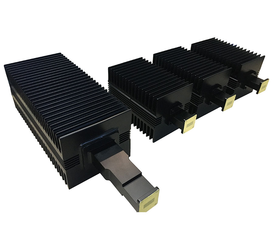
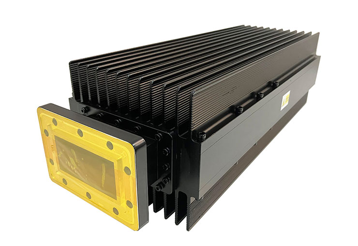
Dolph Microwave's standard product line of low power terminations utilizes precision conical load elements for optimum electrical performance. This series of terminations is designed for low power input. VSWR is less than 1.05 over the full waveguide bandwidth. It is divided into dummy load(low power), high power load, and water load, etc.
Ordering Information of high power load

Ordering Information of low power load

Flange type: Multiple types available - see Dolph Microwave Flanges page.
Finish: Corrosion protection plus black top coat.
Model No* | Freq Range (GHz) | VSWR** (Max) | Avg Power (W) | WG Type | Flange | Material | |
IEC | EIA | ||||||
DH-14WHPL1000… | 1.13-1.73 | 1.20 | 1000 | R14 | WR650 | FDP/FDM | Al |
DH-18WHPL300… | 1.45-2.20 | 1.20 | 300 | R18 | WR510 | FDP/FDM | Al/Cu |
DH-22WHPL250… | 1.72-2.61 | 1.15 | 250 | R22 | WR430 | FDP/FDM | Al/Cu |
DH-26WHPL300… | 2.17-3.30 | 1.15 | 300 | R26 | WR340 | FDP/FDM | Al/Cu |
DH-32WHPL500… | 2.60-3.95 | 1.10 | 500 | R32 | WR284 | FDP/FDM | Al/Cu |
DH-40WHPL300… | 3.22-4.90 | 1.10 | 500 | R40 | WR229 | FDP/FDM | Al/Cu |
DH-48WHPL400… | 3.94-5.99 | 1.10 | 100 | R48 | WR187 | FDP/FDM | Al/Cu |
DH-58WHPL800… | 4.64-7.05 | 1.10 | 800 | R58 | WR159 | FDP/FDM | Al/Cu |
DH-70WHPL500… | 5.38-8.17 | 1.10 | 500 | R70 | WR137 | FDP/FDM | Al/Cu |
DH-84WHPL500… | 6.57-9.99 | 1.10 | 500 | R84 | WR112 | FBP/FBM/FBE | Al/Cu |
DH-100WHPL1000… | 8.20-12.40 | 1.10 | 100 | R100 | WR90 | FBP/FBM/FBE | Al/Cu |
DH-120WHPL400… | 9.84-15.0 | 1.10 | 400 | R120 | WR75 | FBP/FBM/FBE | Al/Cu |
DH-140WHPL500… | 11.9-18.0 | 1.10 | 500 | R140 | WR62 | FBP/FBM/FBE | Al/Cu |
DH-180WHPL50… | 14.5-22.0 | 1.15 | 50 | R180 | WR51 | FBP/FBM/FBE | Al/Cu |
DH-220WHPL200… | 17.6-26.7 | 1.15 | 200 | R220 | WR42 | FBP/FBM/FBE | Al/Cu |
DH-260WHPL100… | 21.7-33.0 | 1.15 | 100 | R260 | WR34 | FBP/FBM/FBE | Al/Cu |
DH-320WHPL30… | 26.3-40.0 | 1.15 | 30 | R320 | WR28 | FBP/FBM/FBE | Al/Cu |
DH-400WHPL20… | 32.9-50.1 | 1.15 | 20 | R400 | WR22 | FUGP | Cu |
*Indicates Model Number. See Ordering Information for complete part number.
**VSWR refers to 30% of waveguide bandwidth.
Termination Type: air-cool, water-type, water cooled type.
Waveguide Size: WR650, WR284, WR137, WR112, WR90, WR75 or others.
Power handling: High power, medium or low power
Duty cycle: Shown as percent.
Flange type: Cover or groove.
Any special requirement, please offer the drawing or dimension for checking.


Waveguide termination is similar to circuits impedance mismatches and electromagnetic waves in waveguides have a similar problem. From the outlook, you can see it is for absorbing signals. If a waveguide junction is in open status, the wave impedance does not match with free space impedance which causes reflection in the system. To avoid this the waveguide must be terminated.
Other Standard Waveguide Components You may have interests in
different types of waveguide attenuators
magic tee in microwave engineering