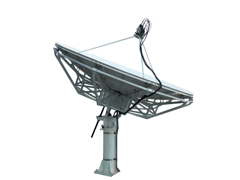
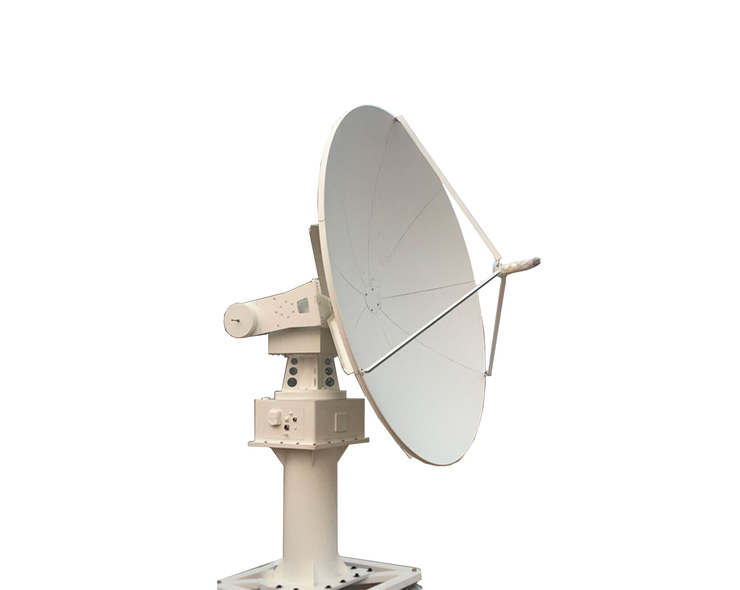
Earth station antenna satellite communications system integrators and designers can bring their systems online faster, more economically, and with superior performance. In use around the world in high-density data, voice, communications networks, and broadcast applications, it is uniquely formed dual reflector Ring-Focus coupled with close-tolerance manufacturing techniques. This combination provides extremely accurate surface contour, exceptionally high gain, superior efficiency, and closely controlled pattern characteristics.
As one of the most professional earth station antenna manufacturers in China, Dolphmicrowave provides earth station antenna with maximum durability and minimal maintenance. The hot-dipped galvanized steel ground mount assembly ensures extended earth station antenna life. Galvanized and stainless steel hardware of earth antenna maximize corrosion resistance. For cost-effective system expansion, available modular equipment options include anti-icing equipment and pressurization systems. Microprocessor Step track Control and motorizable mount options are also available. Diameter and operational frequency range are various. Taking 9.0-meter Earth Station Antenna (ESA) as example.

Antenna diameter: 2.4, 3.7, 4.5, 5.3, 6.3, 7.3 and more
ASIASAT
INTELSAT E-3, E-2, E-1, G
FCC Regulation 25.209
ITU-R, S.580-5 and S.465-5
Antenna type: Tx/Rx or Rx only
Antenna feed: Back feed or prime focus
Frequency range: Ku-band, C-band, Ka-band, dual band or others
Polarization: Linear or circular
Port: 2-port, 4-port or others
Drive mode: Manual or motorized
Tracking mode: Step or monopulse\
For custom satcom antenna with high quality and wide application, Contact Dolph Microwave.
| Technical Specifications | |||||||||
| Feed Configuration | X-Band (Military/WGS) | C-Band | Ku-Band | Ka-Band | |||||
| 2 Port Feed | 2 Port Feed | 2 Port Feed | 2 Port Feed | ||||||
| CP | LP/CP | LP | LP/CP | ||||||
| Receive | Transmit | Receive | Transmit | Receive | Transmit | Receive | Transmit | ||
| Frequency Range | GHz | 7.25–7.75 | 7.9–8.4 | 3.4-4.2 | 5.85-6.725 | 10.7-12.75 | 13.75-14.5 | 17.7-21.2GHz | 27.5-31GHz |
| Mid-Band Gain | dBi | 55.81 | 56.21 | 49.66 | 53.24 | 59.42 | 60.35 | 62.9 | 66.1 |
| VSWR Performance | 1.3:1 | 1.3:1 | 1.3:1 | 1.3:1 | 1.3:1 | 1.3:1 | 1.5:1 | 1.5:1 | |
| 3dB Beam Width | deg | 0.29 | 0.27 | 0.57 | 0.36 | 0.18 | 0.16 | 0.11 | 0.08 |
| Axial ratio | dB | 1.2 | 1.2 | 1.2 | 1.09 | 0.7 | 0.5 | ||
| Antenna Noise Temperature | |||||||||
| 10 Degrees Elevation | Kelvin | 45 | 44 | 53 | 166 | ||||
| 20 Degrees Elevation | Kelvin | 38 | 34 | 43 | 136 | ||||
| Typical G/T @ 10 Degrees | dB/K | 27.2 | 31.2 | 37.1 | 38.7 | ||||
| Tx Power Capability | Watts | 5000 | 10000 | 2000 | 500 | ||||
| Port to Port Isolation | 0 | 110 | 0 | 85 | 0 | 85 | 0 | 85 | |
| Cross-pol on Axis | dB | 23.3 | 23.3 | 35 | 35 | 35 | 35 | 28 | 30.7 |
| Cross-pol across 1dB Beam width | dB | 30 | 30 | 27 | 30 | ||||
| Radiation Pattern Compliance | MIL - STD - 188-164A, DSCS | FCC 25.209, ITU-R S.580-6, | FCC 25.209, ITU-R S.580-6, | FCC 25.209, ITU-R S.580-6, | |||||
| First sidelobe | dBi | ≤ -14 dB | ≤ -14 dB | ≤ -14 dB | ≤ -14 dB | ||||
| Sidelobe Envelope | dBi | 29 - 25 log (1°≤θ<20°) | 29 - 25 log (1°≤θ<20°) | 29 - 25 log (1°≤θ<20°) | 29 - 25 log (1°≤θ<20°) | ||||
| Insertion Loss | dB | 0.5 | 0.5 | 0.3 | 0.5 | 0.4 | 0.5 | 0.5 | 0.6 |
| Feed Interface | WR-112 CPR | WR-112 CPR | WR-229 CPR | WR-137 CPR | WR-75 CPR | WR-75 CPR | WR-42 CPR | WR-28 CPR | |
| MECHANICAL PERFORMANCE | |||||||||
| Antenna Diameter | 9.0 meters (29.6 feet) | ||||||||
| RF Configuration | Compact Cassegrain design | ||||||||
| Reflector Panels | Dual Reflector, 16 precision-formed aluminum panels with heat-diffusing white paint, Cleaned and brightened aluminum back-up structure | ||||||||
| Mount Configuration | Elevation over Azimuth Tripod, or Pedestal, Hot Dipped Galvanized After A36 Steel Fabrication, | ||||||||
| Surface Accuracy (RMS) | 0.35 mm | ||||||||
| Hub Dimensions | |||||||||
| Antenna Foundation | Reinforced Concrete Foundation, or | ||||||||
| Foundation (L x W x D) Concrete Reinforcing Steel | 2800*3000*650mm 7.2m³ 510 kg | ||||||||
| Drive Type | Manual / Motorized jack screw | ||||||||
| Azimuth Travel | 360° Continuous, 40° fine adjustment, Including Az Angle Adjustment Mark, | ||||||||
| Elevation Travel | 0 to 90° Continuous, Mechanical Screw Jack Self Locking, Including El Angle Adjustment Mark, | ||||||||
| Polarization Travel | ±360° | ||||||||
| Rx & Tx cables | 2 RG 6 cables - 10 m (33 ft) each | ||||||||
| Tx Axis transition | Rotary joints, Crossover Waveguides, Twist-Flex Waveguide, | ||||||||
| Total Weight | 1620KG (Not including amplifier, LNB, packing and attachment, etc.) | ||||||||
| Crate Dimensions | Total volume: 10.9CBM | ||||||||
| Shiping Case | 4 Case, Seaworthy Packing ISPM 15, | ||||||||
| Units/40 ft Container | One 20 ft standard (4 units in one 40 ft) | ||||||||
| ENVIRONMENTAL PERFORMANCE | |||||||||
| Operational Wind | 45 mph (72 km/h) gusting to 60 mph (97 km/h), High Wind options available | ||||||||
| Wind speed (with fastening anchors), | 125 mph (200 km/h) @ 58° F (15° C), | ||||||||
| Operational Temperature | +5F to +122F (-15C to +50C), Low Temperature Options Available | ||||||||
| Survival Temperature | -22F to +140F (-30C to +60C), | ||||||||
| Relative Humidity | 100% | ||||||||
| Rain | Up to 4 in/h (10 cm/h) | ||||||||
| Solar Radiation | 360 BTU/hr./ft∧2 (1000 Kcal/hr./m∧2) | ||||||||
| Ice | Operational: .5 in, (2.5 cm) radial, Survival: 1 in,(2.5 cm) radial | ||||||||
| Atmospheric Conditions | As encountered in coastal regions and/or heavily industrialized areas | ||||||||
| Shock and Vibration | As encountered during shipment by airplane, ship or truck | ||||||||
Parabolic Reflector antenna is widely used reflector antenna which according to the structure composition of the microwave photo-like searchlight. Ground station antenna consists reflector, feed system and kingpost. Normally, feed is assembled on focus of reflector.
The reflector curve of earth station antenna is based on parabolic definition and equation. The main parameter of parabolic antenna for sale is focus, diameter and max half field angle. In order to discuss the radiation field and directivity of parabolic antenna, the exit path field must be calculated firstly.
When transmitting, the signal radiates from the feed to the paraboloid, and then radiates into the air after reflecting from the paraboloid. Since the feed is located at the focus of the paraboloid, the radio wave is reflected by the paraboloid and radiated in parallel along the normal direction of the paraboloid. When receiving, after reflected by the reflecting surface, the radio wave converges to the feed source, and the feed source can receive the maximum signal energy.
When high frequency current is applied to the conductor, electric and magnetic fields will be generated in the surrounding space. According to the distribution characteristics of electromagnetic field in space, it can be divided into near zone, middle zone and far zone. Let R be the distance from a point in space to the conductor. When the length L of the conductor is far less than the wavelength, the radiation is very weak; When the length L of the wire is increased to be comparable with the wave length, the current on the wire will be greatly increased, thus forming strong radiation.
High-Accuracy, Aluminum Draw Die Formed Reflector Panels, Self-Aligning Main Reflector.
High Gain, Excellent Pattern Characteristics, Ring-Focus Optics.
C-, X-, Ku-, or K-Band Capabilities, Field Changeable Feed System, C-Band, circular to linear.
Fixed or motorizable pedestals, Antenna control system with tracking.
Reflector and feed deicing systems, Load frame or non-penetrating mounts.
125 mph (200 km/h) Wind Survival in any Position, High Wind (180 mph - 288 km/h) Option.
Low Transportation Costs,Installation Without a Crane.
Packing for sea and air transport, Turnkey installation and testing.
3-Year Warranty on All Structural Components.


The main function of earth station antenna is to collect the weak radio signals emitted by the satellite and send the radio signals containing control commands and data to the satellite, and to remove the clutter signal as much as possible; in general, the larger the satellite ground station antenna diameter, the stronger the signal, The better the reception quality.
The satellite ground antenna widely use included single reflector as prime focus type and dual-reflector antennas (main reflector and sub-reflector). Common dual-reflector antennas include Cassegrain antenna, Gregorian antenna, and ring focus antenna.