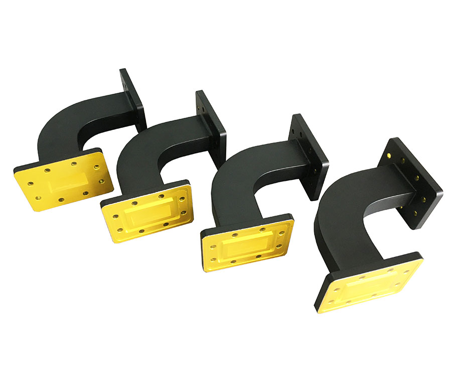
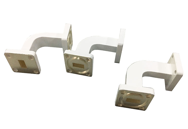
Dolph Microwave offers a standard product line waveguide bends. It is divided into sweep bend and mitered bends covering waveguide sizes WR10 thru WR770. All can be offered both in E-bends and H-bends based on system application. Multi-degrees, additional sizes, configurations and combinations are available on request.
Waveguide Sweep Bends Ordering Information

Waveguide Miter Bends Ordering Information

▪ Flange type: Multiple types available - see Dolph Microwave Flanges page.
▪ Finish: Corrosion protection plus black top coat.
▪ Bends other than 90˚ available on request.
Model No* | Freq Range (GHz) | VSWR (Max) | Std Dimensions A×B×R (mm)** | WG Type | Flange | Material | |
IEC | EIA | ||||||
DH-18WEB… | 1.45-2.20GHz waveguide bends | 1.15 | 290×290×135 | R18 | WR510 | FDP/FDM | Al/Cu |
DH-18WHB… | 1.45-2.20GHz waveguide bends | 1.15 | 350×350×192 | R18 | WR510 | FDP/FDM | Al/Cu |
DH-22WEB… | 1.72-2.61GHz waveguide bends | 1.15 | 190×190×95 | R22 | WR430 | FDH/FDM | Al/Cu |
DH-22WHB… | 1.72-2.61GHz waveguide bends | 1.15 | 250×250×152 | R22 | WR430 | FDH/FDM | Al/Cu |
DH-26WEB… | 2.17-3.30GHz waveguide bends | 1.15 | 100×100×40 | R26 | WR340 | FDH/FDM | Al/Cu |
DH-26WHB… | 2.17-3.30GHz waveguide bends | 1.15 | 180×180×100 | R26 | WR340 | FDH/FDM | Al/Cu |
DH-32WEB… | 2.60-3.95GHz waveguide bends | 1.10 | 100×100×40 | R32 | WR284 | FDH/FDM | Al/Cu |
DH-32WHB… | 2.60-3.95GHz waveguide bends | 1.10 | 160×160×100 | R32 | WR284 | FDH/FDM | Al/Cu |
DH-40WEB… | 3.22-4.90GHz waveguide bends | 1.10 | 80×80×40 | R40 | WR229 | FDH/FDM | Al/Cu |
DH-40WHB… | 3.22-4.90GHz waveguide bends | 1.10 | 120×120×78 | R40 | WR229 | FDH/FDM | Al/Cu |
DH-48WEB… | 3.94-5.99GHz waveguide bends | 1.10 | 80×80×40 | R48 | WR187 | FDH/FDM | Al/Cu |
DH-48WHB… | 3.94-5.99GHz waveguide bends | 1.10 | 80×80×40 | R48 | WR187 | FDH/FDM | Al/Cu |
DH-58WEB… | 4.64-7.05GHz waveguide bends | 1.10 | 80×80×40 | R58 | WR159 | FDH/FDM | Al/Cu |
DH-58WHB… | 4.64-7.05GHz waveguide bends | 1.10 | 80×80×40 | R58 | WR159 | FDH/FDM | Al/Cu |
DH-70WEB… | 5.38-8.17GHz waveguide bends | 1.10 | 60×60×30 | R70 | WR137 | FDH/FDM | Al/Cu |
DH-70WHB… | 5.38-8.17GHz waveguide bends | 1.10 | 80×80×50 | R70 | WR137 | FDH/FDM | Al/Cu |
DH-84WEB… | 6.57-9.99GHz waveguide bends | 1.10 | 50×50×25 | R84 | WR112 | FBP/FBM/FBE | Al/Cu |
DH-84WHB… | 6.57-9.99GHz waveguide bends | 1.10 | 60×60×35 | R84 | WR112 | FBP/FBM/FBE | Al/Cu |
DH-100WEB… | 8.20-12.40GHz waveguide bends | 1.10 | 40×40×20 | R100 | WR90 | FBP/FBM/FBE | Al/Cu |
DH-100WHB… | 8.20-12.40GHz waveguide bends | 1.10 | 55×55×35 | R100 | WR90 | FBP/FBM/FBE | Al/Cu |
DH-120WEB… | 9.84-15.0GHz waveguide bends | 1.10 | 40×40×20 | R120 | WR75 | FBP/FBM/FBE | Al/Cu |
DH-120WHB… | 9.84-15.0GHz waveguide bends | 1.10 | 45×45×30 | R120 | WR75 | FBP/FBM/FBE | Al/Cu |
DH-140WEB… | 11.9-18.0GHz waveguide bends | 1.10 | 40×40×20 | R140 | WR62 | FBP/FBM/FBE | Al/Cu |
DH-140WHB… | 11.9-18.0GHz waveguide bends | 1.10 | 40×40×25 | R140 | WR62 | FBP/FBM/FBE | Al/Cu |
DH-180WEB… | 14.5-22.0GHz waveguide bends | 1.10 | 30×30×15 | R180 | WR51 | FBP/FBM/FBE | Al/Cu |
DH-180WHB… | 14.5-22.0GHz waveguide bends | 1.10 | 35×35×20 | R180 | WR51 | FBP/FBM/FBE | Al/Cu |
DH-220WEB… | 17.6-26.7GHz waveguide bends | 1.15 | 30×30×15 | R220 | WR42 | FBP/FBM/FBE | Al/Cu |
DH-220WHB… | 17.6-26.7GHz waveguide bends | 1.15 | 35×35×20 | R220 | WR42 | FBP/FBM/FBE | Al/Cu |
DH-260WEB… | 21.7-33.0GHz waveguide bends | 1.15 | 30×30×15 | R260 | WR34 | FBP/FBM/FBE | Al/Cu |
DH-260WHB… | 21.7-33.0GHz waveguide bends | 1.15 | 35×35×20 | R260 | WR34 | FBP/FBM/FBE | Al/Cu |
DH-320WEB… | 26.3-40.0GHz waveguide bends | 1.15 | 25×25×10 | R320 | WR28 | FBP/FBM/FBE | Al/Cu |
DH-320WHB… | 26.3-40.0GHz waveguide bends | 1.15 | 30×30×15 | R320 | WR28 | FBP/FBM/FBE | Al/Cu |
DH-400WEB… | 32.9-50.1GHz waveguide bends | 1.20 | 25×25×10 | R400 | WR22 | FUGP | Cu |
DH-400WHB… | 32.9-50.1GHz waveguide bends | 1.20 | 20×20×10 | R400 | WR22 | FUGP | Cu |
DH-500WEB… | 39.2-59.6GHz waveguide bends | 1.20 | 25×25×10 | R500 | WR19 | FUGP | Cu |
DH-500WHB… | 39.2-59.6GHz waveguide bends | 1.20 | 25×25×10 | R500 | WR19 | FUGP | Cu |
DH-620WEB… | 49.8-75.8GHz waveguide bends | 1.20 | 20×20×10 | R620 | WR15 | FUGP | Cu |
DH-620WHB… | 49.8-75.8GHz waveguide bends | 1.20 | 25×25×10 | R620 | WR15 | FUGP | Cu |
*Indicates Model Number. See Ordering Information for complete part number.
**Legs (A, B) available in other sizes. Consult sales engineer for more information.
E bend
Waveguide E bend is to change the electric field so that the waveguide is bent in the required direction which is to avoid reflections. This type of bend requires the radius must be greater than two wavelengths.
H bend
Waveguide H-bend is very close to the E bend, but it distorts the H or magnetic field which only happens to the bend around the thinner side of the waveguide.
Sharp E bend
In some assemble limited conditions, a much shorter or sharper bend is required. This can be accomplished in a slightly different method of production technology. Using a 45° surface the reflections occur in such a way that the fields are not disturbed.
Sharp H bend
Sharp waveguide H bend is the same as the sharp E bend, the only difference is it is aimed to affect the H field rather than the E field.


Waveguide bends can be divided into E bend, H bend, sharp E bend and sharp H bend
Each type of bend is the same function which is to enable the signal to transmit correctly and with the minimum of interference to the fields and the overall signal.
The most common bend requirements are 90° and 45°. But other requirements for waveguide bends can also be offered based on requirements.
As a professional waveguide components supplier in China, Dolph Microwave also provides quality custom microwave components for your needs. Feel free to contact us at any time if you have any other thought regarding custom waveguide bends.
Other Standard Waveguide Components You may have interests in
different types of waveguide attenuators
magic tee in microwave engineering