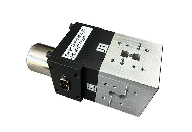
Dolph Microwave series model's frequency are covering from 2.60 GHz to 110GHz. Usually, in accordance with drive modes, they can be classified into sub-electric and manual; If by structure, they are classified into sub-E and H-waveguide transfer switches, with rectangular waveguide transfer switches and double ridge waveguide transfer switches. Wave guide switch is commonly used to change the signal pathway in the waveguide transmission system. Taking WRD750 type as below.

Flange type: Multiple types available - see Dolph Microwave Flanges page.
Finish: Corrosion protection plus black top coat.
For custom ridged waveguide with high quality and wide application, contact Dolph Microwave.
| WRD750 Waveguide Electronic Switch | |
| Electrical Specifications | |
| Model | DH-750DWESMDC |
| Frequency Range | 7.5-18.0 GHz waveguide switch |
| VSWR | ≤1.3:1 |
| Isolation | ≥50 dB |
| IL | ≤0.4 dB |
| Handling Power | 2000 W (CW) |
| Switch Speed | 120ms |
| Switch Type | Double Pole Double Throw (DPDT) |
| Actuator Type | Latching |
| Actuator Options | TTL Logic, Self Cut Off, Window Indicator, |
| TTL Control | on: 2.4 to 5.5 Volts |
| off: 2.4 to 5.5 Volts | |
| Power Voltage | 27V±10% ( 0.5A ) |
| Control Interface | 6-pin Aviation Plug (Customizable) |
| Life | ≥100,000 Cycles |
| Mechanical Specifications | |
| Waveguide Type | WRD750 |
| Flange | FPWRD750D24 |
| Ingress Protection Rating | IP67 |
| Pressure | Up to 30 PSIG |
| Temperature | -40℃~+80℃ |
| Humidity | 0-100% |
| Material | Al/Cu |
| Inside Finish | Conductive Oxidation |
| Outside Finish | Anticorrosion Grey Paint |
Control Interface Specification
MS3102E14S-6P Connector Pin Instructions
| Pin Number | A | B | C | D | E | F |
| Purpose | Power supply/grounding | Grounding/power supply | Connect to micro switch | Connect to micro switch | Connect to micro switch | Connect to micro switch |
Waveguide Sitch Control Interface Signal Definition
| MS3102E14S-6P | Definition | Description |
| A | Power supply/grounding | Switching power supply, when A is connected to +27V and B is grounded for a duration of 120ms±20ms, the switch is in state I (J0 and J1, J2 and J3 are on). |
| B | Grounding/power supply | Switching the power supply, when A is grounded, B is connected to +27V, and the duration is 120ms±20ms, the switch is in state II (J0 and J2, J1 and J3 are on). |
| C | Connect to micro switch | Switch state signal, when the switch is in state I, pins C and D are turned on. |
| D | Connect to micro switch | It is recommended to connect the signal voltage +5V (connect a 100Ω resistor in series) |
| E | Connect to micro switch | It is recommended to connect the signal voltage +5V (connect a 100Ω resistor in series) |
| F | Connect to micro switch | Switch state signal, when the switch is in state II, pins E and F are turned on. |
A waveguide transfer switch is used to route signals from an input path to one or more outputs. Waveguide transfer switch operates in GHz range and are ideal for use in switching applications in microwave communications, broadcasting, radar applications, and many more applications.
Wave guide switch is the operating frequency range for which the device is fully functional or provides the best performance. This waveguide transfer switch is available in waveguide-to-waveguide interface. Switching includes SPST, SPDT, DPDT, SP3T, SP4T, SP6T, etc. The separation of signal levels on adjacent ports of the waveguide switch and is expressed in dB.

The double ridge waveguide switches have higher-performing switch mechanisms. With a double-ridged waveguide, a nearly complete short circuit can be made by merely bridging the reduced distance between the ridges. It places switching elements within the gap of the ridges.
The double ridge waveguide transfer switches are mainly used for changing the signal channel of the waveguide transmission system, according to drive mode which is divided into motorized and manual.
Click waveguide bulkhead for more information
Others you may be interested in: