Waveguide switch, commonly used to change the signal pathway in the waveguide transmission system, usually, in accordance with drive modes, they can be classified into sub-electric and manual; If by structure, they are classified into sub-E and H- waveguide switches, with rectangular waveguide switches and double ridge waveguide switches. DH series models frequency are covering from 2.60 GHz to 110GHz. Features with high stability, good accuracy and fast response. Taking WR28 type as example as below.

Control Interface Specification
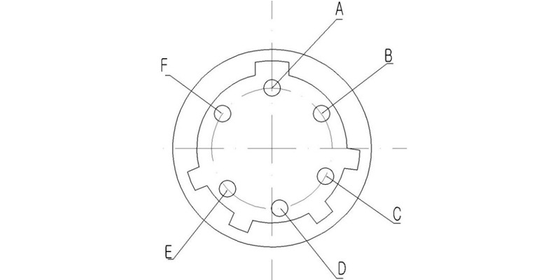
Aviation Plug 6-pin layout.
No. | Definition | Description |
A | Power | Switching the power supply, when A is connected to +24V and B is grounded for a duration of 120ms ± 20ms, the switch is in state I (J0 and J1, J2 and J3 are on). |
B | Ground | Ground |
C | +24V | Switching the power supply, when C is connected to +24V and B is grounded for a duration of 120ms ± 20ms, the switch is in state II (J0 and J2, J1 and J3 are on). |
D | Connect to Micro Switch | State I and E are turned on |
E | Connect to Micro Switch | Ground |
F | Connect to Micro Switch | State II and E are turned on |
Test Data
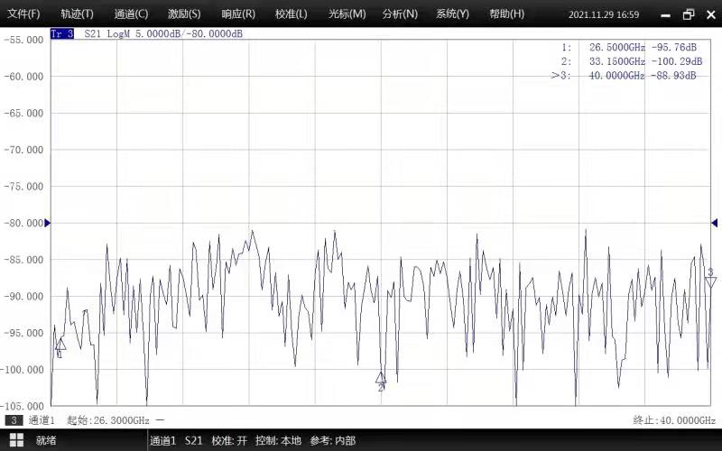
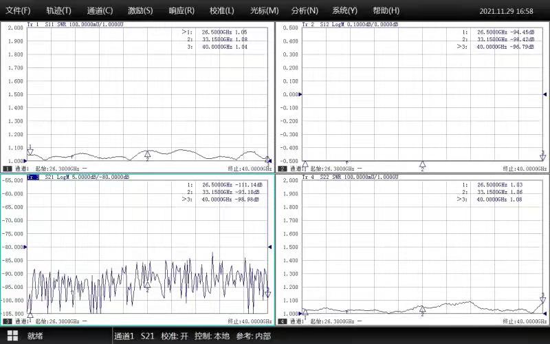
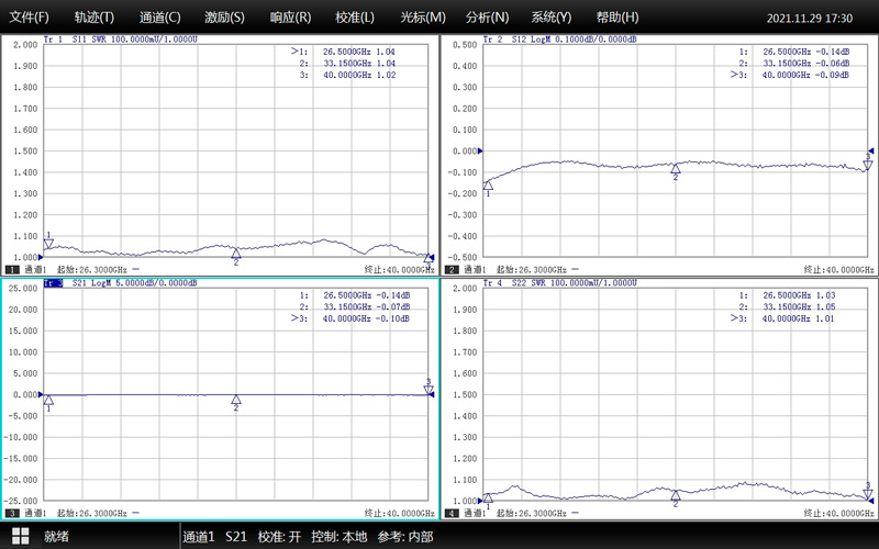
WR28 Waveguide Electronic Switch | |
Electrical Specifications | |
Model | DH-320WESMD |
Frequency Range | 26.5-40.0 GHz |
VSWR | ≤1.15:1 |
Isolation | ≥80 dB |
IL | ≤0.15 dB |
Handling Power, CW | ≥1000 W |
Conversion Time | ≤120 ms |
Power Voltage | 24V±10% |
Current | ≤1.0 A |
Actuator Type | Latching |
Actuator Options | TTL Logic, Self Cut Off, Window Indicator, Manual Override |
TTL Control | on: 2.4 to 5.5 Volts off: 2.4 to 5.5 Volts |
Control Interface | 6-pin Aviation Plug (Customizable) |
Mechanical Specifications | |
Waveguide Type | BJ320(WR28) |
Flange | FBP320 |
Switch Type | DPDT, SPDT |
Waveguide Ports | 0,1,2,3. the identification of 4 waveguide ports |
Switch Position | Position 1, Position 2 |
Position 1 | Waveguide Port 0-1 pass / 2-3 pass |
Position 2 | Waveguide Port 0-2 pass / 1-3 pass |
Tightness Class | IP 56 |
Material | Al |
Inside Finish | Conductive oxidation |
Outside Finish | Anticorrosion Black Paint |
Temperature | -40℃~+85℃ |
Waveguide switch is available in various waveguide sizes. Following specifications need to be consider for selection of the waveguide switch.
Frequency range.
Current consumption.
Conversion/Switching time.
Isolation/ Insertion Loss/VSWR in dB.
Power handling capability with duty cycle in percent.
Switch type: SPDT or DPDT or others.
Control mode and interface.
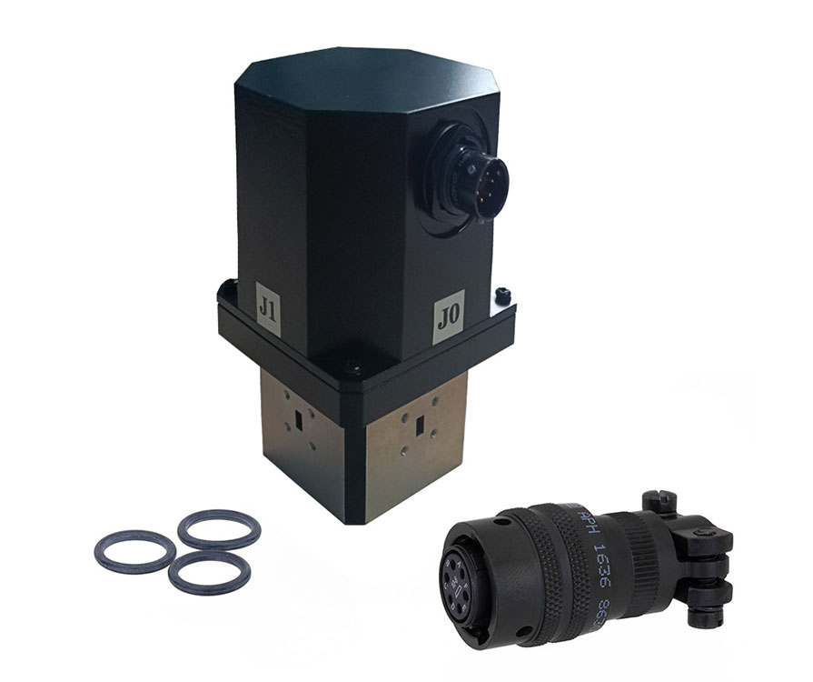
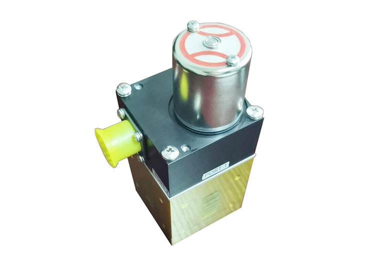
Waveguide RF switches are electromagnetic switches for transmitting RF energy in many field including microwave communications, satcom industry and in radar applications. Waveguide switches can be used to transfer both power and communication signals and the bandwidth, and related to the waveguide type like WR137, WR28, WR62, etc. Waveguides can route extremely high power signals over a narrow bandwidth at low to high frequencies with light weight.
Other Standard Waveguide Components You may have interests in
different types of waveguide attenuators
magic tee in microwave engineering