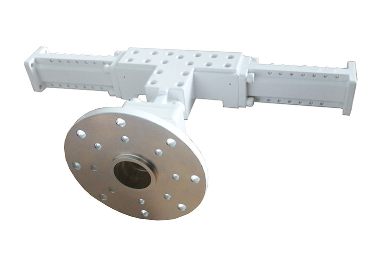
Dolph has developed a comprehensive line of waveguide ortho-mode transducer covering C, X, Ku and Ka bands. The devices offer very high performance at a very competitive price. Orthomode Transducers separate a signal applied to the circular waveguide input port into its two linear orthogonal components at the rectangular waveguide output ports between the polarizations. In reverse, two orthogonal linearly polarized signals combine, producing an output in the circular waveguide port. The resulting polarization may be linear, circular, or elliptical depending on the relative phase and amplitude of the two orthogonal input signals. Please call us with your specification and discuss your needs with one of our sales engineers.
Note: Take Ka-Band Waveguide Ortho-Mode Transducer (OMT) as an example.

| Ka-Band Waveguide Ortho-Mode Transducer (OMT) | ||
| Model: DH-OMT-Ext.Ka-RT-X-01 | WR42/WR28 Waveguide Ortho-Mode Transducer 2-port | |
| 17.7 GHz to 21.2 GHz/27.5 GHz to 31.0GHz | ||
| Cross Linear Polarization | ||
| Frequency Range | Rx 17.7 to 21.2 GHz / Tx 27.5 to 31.0GHz | |
| VSWR | 1.25:1 | |
| Insertion Loss | Tx 0.1 dB / Rx 0.15 dB | |
| Cross pol | 35 dB | |
| Isolation between Ports 1 to 2 (Tx Freq) | 35 dB min. | |
| Power handling | max. 500 W CW each port | |
| Waveguide size | R220 / WR42, R320 / WR28, | |
| Flanges Port 1,2 | FBP220 / FBP320 | |
| Common Port | Circular waveguide φ11.2mm | |
| Material | Aluminum, conductive oxidation | |
| Finish | Black/White Paint (standard) | |
| Operating Temperature | -40° C to 70° C | |
| Additional Feature | I-type rotary joint with integrated drive system are available Additional Feature for polarization control adjustment (Option) | |

An Orthogonal Mode Transducer (OMT) is a waveguide component commonly referred to as a polarization duplexer. Orthogonal mode transducers are used to combine or split two orthogonally polarized microwave signal paths. One of the paths forms the uplink and travels through the same waveguide as the receive signal path or downlink path.
Orthogonal mode transducers are used to combine or separate two orthogonally polarized microwave signal paths. One of the paths forms the uplink and travels through the same waveguide as the receive signal path or downlink path. Such equipment may be part of a Very Small Aperture Terminal (VSAT) antenna feed or a terrestrial microwave radio feed; for example, OMTs are often used with feed horns to isolate orthogonal polarizations of signals and transmit transmit and receive signals to different ports.
Other antenna feeds with high quality and wide applications.