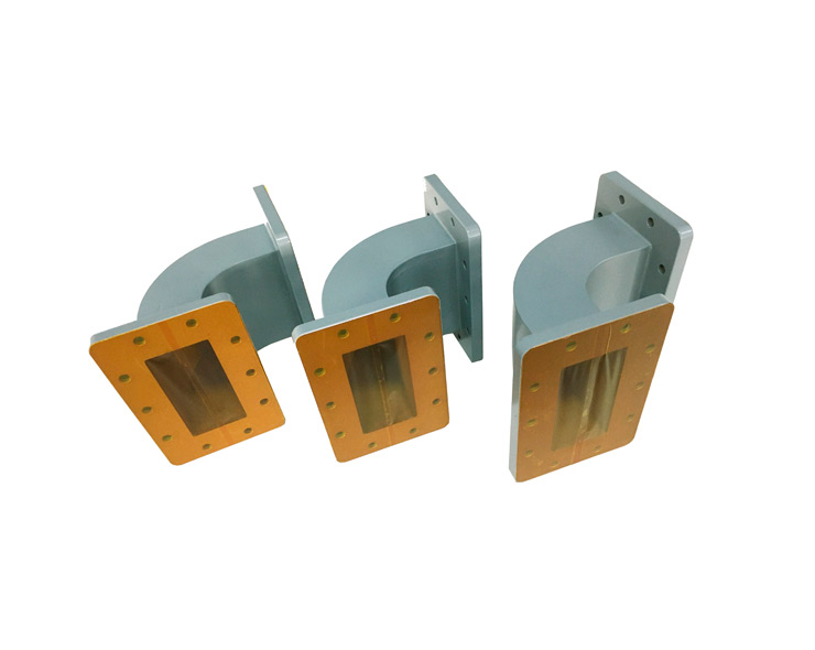
Dolph Microwave offers Industrial Microwave Bends for 915 and 2450MHz, which includes both E-bends and H-bends. All units are precisely bending to the desired angle. At the same time, maintaining a constant cross section to minimize energy reflection. Besides, this family of Industrial Microwave Bends, also boast low loss, and VSWR as low as 1.06:1 and are available in both E-bends and H-bends configurations. Taking the WR340(2450MHz) for example.

WR340 Waveguide Bend | |
Electrical Specifications | |
Model | DH-26WHB/WEB_A*B |
Frequency Range | 2.17-3.3 GHz |
VSWR | ≤1.1:1 |
Insertion Loss | ≤0.05 dB |
Mechanical Specifications | |
Waveguide Type | WR340 |
Type of Bend | H-Bend/E-Bend |
Flange Type | FBP26 (Cover)/FBM26 (Grooved) |
Material | Aluminum |
Inside Finish | Conductive Oxidation |
Outside Finish | Anticorrosion Black/White Paint |
Size(mm) | A=** mm, B=** mm |
Dolph Microwave specializes in waveguide solutions, including microwave E-bends and microwave H-bends, crucial components with distinct characteristics in the realm of microwave technology.
Microwave Waveguide E bend
Microwave E-bend refers to the bending of the wider section of the waveguide, causing a change in the electric field. It is often termed as bending in the "easy" direction. This alteration in the electric field can lead to distortion, and microwave E-bends are particularly relevant when maintaining the polarization of electromagnetic waves is essential. Dolph Microwave's E-bends are meticulously crafted to minimize signal loss and distortion during this bending process, ensuring high fidelity in signal transmission. The direction of change in the electric field occurs along the broader section of the waveguide.
Microwave Waveguide H bend
In contrast, microwave H-bend involves bending the narrower section of the waveguide, causing a change in the magnetic field. Described as bending in the "difficult" direction, microwave H-bends are critical in scenarios where space constraints or specific system layouts necessitate bending along the narrower dimension of the waveguide. Dolph Microwave's H-bends are designed to handle this type of bending with precision, ensuring optimal performance even when subjected to sharp turns. The direction of change in the magnetic field occurs along the narrower section of the waveguide.
In summary, Dolph Microwave's expertise lies in providing comprehensive solutions for waveguide systems, accommodating both microwave E and H bends. These microwave bends, based on the direction of change in the electric and magnetic fields respectively, contribute to the company's commitment to delivering high-quality and versatile waveguide components for diverse microwave applications.

Industrial Microwave Bends are used to guide high-frequency signals propagating in a specific direction through the waveguide. Because of these bends, the signal is allowed to change direction within the waveguide, thereby minimizing losses, reflections, and distortions in the electric and magnetic fields.
Industrial Microwave Bends include E-bends and H-bends. E-bends alter or distort the E-field (electric field) of a propagating signal. H-bends alter or distorts the H-field (magnetic field) of a propagating signal. The bend angle is usually 30, 45, or 90 degrees.
More industrial microwave components may interest you